Hermes とか llama3 のtool_calling で MCP を使うメモ
最近 Local LLM でオレオレ LLM 環境を作ろうといろいろ調べている中で、 Local LLM から MCP 使えると便利だよねでやったこと
tool calling
Local LLM で tool calling というのがある。
生プロンプトでの例
一例として、Hermes の tool calling だと(Qwenとかもおなじ)
system prompt
You are a function calling AI model. You are provided with function signatures within <tools> </tools> XML tags. You may call one or more functions to assist with the user query. If available tools are not relevant in assisting with user query, just respond in natural conversational language. Don't make assumptions about what values to plug into functions. After calling & executing the functions, you will be provided with function results within <tool_response> </tool_response> XML tags.
<tools>
[{'type': 'function', 'function': {'name': 'get_stock_fundamentals', 'description': 'Get fundamental data for a given stock symbol using yfinance API.', 'parameters': {'type': 'object', 'properties': {'symbol': {'type': 'string'}}, 'required': ['symbol']}}}]
</tools>
For each function call return a JSON object, with the following pydantic model json schema:
{'title': 'FunctionCall', 'type': 'object', 'properties': {'name': {'title': 'Name', 'type': 'string'}, 'arguments': {'title': 'Arguments', 'type': 'object'}}, 'required': ['arguments', 'name']}
Each function call should be enclosed within <tool_call> </tool_call> XML tags. You must use <scratch_pad> </scratch_pad> XML tags to record your reasoning and planning before you call the functions as follows.
Example:
<scratch_pad>
Goal: <state task assigned by user>
Actions:
<if tool calls need to be generated:>
- {result_var_name1} = functions.{function_name1}({param1}={value1},...)
- {result_var_name2, result_var_name3} = ...
<if no tool call needs to be generated:> None
Observation: <set observation 'None' with tool calls; plan final tools results summary when provided>
Reflection: <evaluate query-tool relevance and required parameters when tools called; analyze overall task status when observations made>
</scratch_pad>
<tool_call>
{'name': <function-name>, 'arguments': <args-dict>}
</tool_call>
こんなものを流すと
<|im_start|>user
Fetch the stock fundamentals data for Tesla (TSLA)<|im_end|>
<|im_start|>assistant
<tool_call>
{'arguments': {'symbol': 'TSLA'}, 'name': 'get_stock_fundamentals'}
</tool_call><|im_end|>
こんなかんじで JSON が返ってくるので、これを拾って
<|im_start|>tool
<tool_response>
{"name": "get_stock_fundamentals", "content": {'symbol': 'TSLA', 'company_name': 'Tesla, Inc.', 'sector': 'Consumer Cyclical', 'industry': 'Auto Manufacturers', 'market_cap': 611384164352, 'pe_ratio': 49.604652, 'pb_ratio': 9.762013, 'dividend_yield': None, 'eps': 4.3, 'beta': 2.427, '52_week_high': 299.29, '52_week_low': 152.37}}
</tool_response>
<|im_end|>
こんな感じでツール実行結果を返してあげると、この内容を解釈して LLM が結果を返してくれる仕組み。
transformers で chat templete を使う例
それで、これは面倒なんだけど、大体 chat templete を使うと tool 一覧を json で渡してあげるといい感じでやってくれる。
たとえば huggingface の transformers だと、
# A simple function that takes no arguments
current_time = {
  "type": "function",
  "function": {
    "name": "current_time",
    "description": "Get the current local time as a string.",
    "parameters": {
      'type': 'object',
      'properties': {}
    }
  }
}

# A more complete function that takes two numerical arguments
multiply = {
  'type': 'function',
  'function': {
    'name': 'multiply',
    'description': 'A function that multiplies two numbers',
    'parameters': {
      'type': 'object',
      'properties': {
        'a': {
          'type': 'number',
          'description': 'The first number to multiply'
        },
        'b': {
          'type': 'number', 'description': 'The second number to multiply'
        }
      },
      'required': ['a', 'b']
    }
  }
}

model_input = tokenizer.apply_chat_template(
    messages,
    tools = [current_time, multiply]
)
こんなかんじで名前や properties を apply_chat_templete で渡してあげると前述のコードを出してくれる。
対応モデルは、vLLM のこのページとかが参考になる。
個別モデルでは、chat_templete.json を見れば使えるかがわかる。
OpenAI API を使う方法
Ollama や Llama.cpp とかで使える OpenAI API でも同じフォーマットの json が使える。
OpenAI API の場合は、client.responses.create に tools として渡す。
from openai import OpenAI

client = OpenAI()

tools = [{
    "type": "function",
    "name": "get_weather",
    "description": "Get current temperature for a given location.",
    "parameters": {
        "type": "object",
        "properties": {
            "location": {
                "type": "string",
                "description": "City and country e.g. Bogotá, Colombia"
            }
        },
        "required": [
            "location"
        ],
        "additionalProperties": False
    }
}]

response = client.responses.create(
    model="gpt-4.1",
    input=[{"role": "user", "content": "What is the weather like in Paris today?"}],
    tools=tools
)

print(response.output)
私は OpenAI の API が使えないので、Ollama で使える API で同じようなことをした結果を参考に貼っておくと
# Ollama では client.responses が実装されていないので、 client.chat.completions で代替
stream = client.chat.completions.create(
    messages=messages,
    model='rinna-qwq-q4',
    tools=tools
)
以下のような形で帰ってくる。これは client.responses の場合少し違う結果になるけど、OpenAI のドキュメントを読んでもらえば多分わかる。
ChatCompletion(id='chatcmpl-243', choices=[Choice(finish_reason='tool_calls', index=0, logprobs=None, message=ChatCompletionMessage(content='', refusal=None, role='assistant', annotations=None, audio=None, function_call=None, tool_calls=[ChatCompletionMessageToolCall(id='call_n36j4m54', function=Function(arguments='{"url":"https://docs.vllm.ai/en/stable/features/tool_calling.html#llama-models-llama3-json"}', name='fetch'), type='function', index=0)]))], created=1745092883, model='rinna-qwq-q4k:latest', object='chat.completion', service_tier=None, system_fingerprint='fp_ollama', usage=CompletionUsage(completion_tokens=329, prompt_tokens=3097, total_tokens=3426, completion_tokens_details=None, prompt_tokens_details=None))
MCP を tool_calling と連携する
モデルを初期化する前に、MCP のツールリストを取得して、tools として渡してあげると認識して使ってくれるようになる。
リストを取得する例
server_config = config.load_config("servers_config.json")
for name, srv_config in server_config["mcpServers"].items():
    mcp_server = Server(name, srv_config)
    mcp_servers.append(mcp_server)
    mcp_servers_dict[name] = mcp_server
for server in mcp_servers:
    try:
        await server.initialize()
    except Exception as e:
        logging.error(f"Failed to initialize server: {e}")
        for server in mcp_servers:
            await server.cleanup()
        return
all_tools = []
for server in mcp_servers:
    tools = await server.list_tools()
    all_tools.extend(tools)
def format_for_llm(self) -> str:
    """Format tool information for LLM.

    Returns:
        A formatted string describing the tool.
    """
    output = {
        "type": "function",
        "function": {
            "name": self.name,
            "description": self.description,
            "parameters": {"type":"object","properties":{}}}}
    for key, value in self.input_schema["properties"].items():
        output['function']['parameters']['properties'][key] = {
            "type": value['type'],
            "description": value['description']
        }

    if self.input_schema.get('required', []):
        output['function']['required'] = self.input_schema['required']
    return output
これで、LLM が MCP のツールを使おうとすると JSON でリクエストを出してくれるので、それを拾うといいかんじになる。
ほか
- Spring を使うと、この辺が楽にできるらしい。
- ik.am
- gemma3 は tools を chat_template で受け付けてないのにどうしているのかは謎
VIVE Base Station 1.0の信号仕様と実際の信号
ふと思いいたってVIVE Base Stationを作ることになった。
本当は2.0が作りたいけどとりあえず1.0のほうが資料が多かったので、調査と試作にあたっての実物の信号を計測した。
本当はモックを試作したけど動かなかった。
VIVE Base Station 1.0の仕様
この分野には若干の先人がいる
note.com
www.youtube.com
github.com
github.com
この辺から情報を調べた。また、公式の情報は参照していない。
位置特定の仕組み
Base Station 1.0の仕組みは以下の動画がわかりやすい。
あるBase StationからみたX方向の角度を把握する流れは次のようになっている。
- 部屋全体を照らす高輝度LEDを一瞬光らせる(走査開始の信号)
- X or Y方向に等速回転する線レーザー(Line Lensで直線に引き伸ばされたレーザー)で部屋全体を走査する
これをX, Yの順で交互に実施する。
この結果、走査開始の信号を受信してから、レーザー光を受信するまでの時間を計測すれば、X方向/Y方向のBase Stationからの角度がわかる。
そして、2つのBase Stationは対角に設置されているため、2つのBase Stationからの角度が分かれば空間内の位置が特定できるという算段らしい。
X方向だけで見るとこんな感じ。

あるトラッカーの位置を特定するプロセスを整理すると
- Base Station 1からのX方向の角度を走査
- Base Station 1からのY方向の角度を走査
- Base Station 2からのX方向の角度を走査
- Base Station 2からのY方向の角度を走査
という流れになる。
このレーザーはそれぞれ60Hzで回転しており、またXとYは180度ズレて回転している。なので走査周期は120Hzとなる。そのため、物体の位置は30Hzで更新されていることがわかる。
またこの挙動の把握には以下の資料も非常に参考になった。
走査開始信号の仕様
この詳細はこのページに情報がある。この辺になると読めばいいじゃんと思わなくもないが、日本語資料が無く、また分かりにくい点もあったので解説する。
走査開始信号は、立ち上がりが走査レーザーが0度であることを通知する信号である。他方で、光っている長さに3bitの情報が含まれている。
| Name | skip | data | axis | length (ticks) | length (µs) |
|---|---|---|---|---|---|
| j0 | 0 | 0 | 0 | 3000 | 62.5 |
| k0 | 0 | 0 | 1 | 3500 | 72.9 |
| j1 | 0 | 1 | 0 | 4000 | 83.3 |
| k1 | 0 | 1 | 1 | 4500 | 93.8 |
| j2 | 1 | 0 | 0 | 5000 | 104 |
| k2 | 1 | 0 | 1 | 5500 | 115 |
| j3 | 1 | 1 | 0 | 6000 | 125 |
| k3 | 1 | 1 | 1 | 6500 | 135 |
このbitについて説明すると
- skip: レーザーが出ているか。0でON、1でOFF
- data: データ転送に使う。0/1の1bit情報
- axis: レーザーの方向。0でX、1でY
skipについて補足すると、一般にBase Station 1.0では2つのBase Stationを利用する。そのため、片方のBase Stationがレーザーを飛ばしているときは、もう片方のBase Stationはレーザーを止めないとどちらのレーザーかわからなくなるためその際に利用されている。
そのためあるBase Stationの出力信号は送信データの内容に依存して
- j0 or j1
- k0 or j1
- j2 or j3
- k2 or k3
の順番で送られることとなる。
データ仕様
ザーッと書いていく。
正直文字だけだとわかりにくいので最後に実際に手元のBase Station 1.0から受信した実データを置いておくので安心してほしい。
図をもっと使ったほうがわかりやすいけど気が向いたら....
OOTX(Omnidirectional Optical Transmitter) Frameの仕様
前章と同じく以下を参照する。
OOTXとは、前章の走査開始信号におけるdata bitで送信される内容である。
構造は以下の通り。
| Preamble | Payload Length | S | Payload | CRC32 |
- Preamble(18bit)
- 18bitで0x001
- Preamble以外では、16bitに1bitの間隔でSync Bit(1の値)が挟まる。そのためPreamble以外で17bitの0が続くことがないため、これで先頭を判断する
- Payload Lenght(16bit)
- そのまま、Payload Length
- Base Station 1.0ではBase Station Info Block以外に送信するデータがないため、0x21で固定
- このPayload LengthにはPadding byteを含まない
- S(1bit)
- Sync Bit
- Payload(34bytes+17bits)
- CRC32(2bytes + 2bits)
- PayloadのCRC32
- Padding byteもSync BitもPayload Lengthも含まない
Base Station Info Block
ここを参照した。
| 0x00 | uint16 | fw_version | Firmware version (bit 15..6), protocol version (bit 5..0) |
| 0x02 | uint32 | ID | Unique identifier of the base station |
| 0x06 | float16 | fcal.0.phase | "phase" for rotor 0 |
| 0x08 | float16 | fcal.1.phase | "phase" for rotor 1 |
| 0x0A | float16 | fcal.0.tilt | "tilt" for rotor 0 |
| 0x0C | float16 | fcal.1.tilt | "tilt" for rotor 1 |
| 0x0E | uint8 | sys.unlock_count | Lowest 8 bits of the rotor desynchronization counter |
| 0x0F | uint8 | hw_version | Hardware version |
| 0x10 | float16 | fcal.0.curve | "curve" for rotor 0 |
| 0x12 | float16 | fcal.1.curve | "curve" for rotor 1 |
| 0x14 | int8 | accel.dir_x | "orientation vector" |
| 0x15 | int8 | accel.dir_y | "orientation vector" |
| 0x16 | int8 | accel.dir_z | "orientation vector" |
| 0x17 | float16 | fcal.0.gibphase | "gibbous phase" for rotor 0 (normalized angle) |
| 0x19 | float16 | fcal.1.gibphase | "gibbous phase" for rotor 1 (normalized angle) |
| 0x1B | float16 | fcal.0.gibmag | "gibbous magnitude" for rotor 0 |
| 0x1D | float16 | fcal.1.gibmag | "gibbous magnitude" for rotor 1 |
| 0x1F | uint8 | mode.current | Currently selected mode (default: 0=A, 1=B, 2=C) |
| 0x20 | uint8 | sys.faults | "fault detect flags" (should be 0) |
- Protocol Version
- 6固定
- ID
- Base Stationの裏に書いてあるシリアルID
- phase/tilt/curve/gibbous phase/gibbous magnitude
- レーザー補正用のパラメータだと思われる
- accel
- 加速度センサー。Base Stationの向きを特定するのに使っていると思われる
- mode
- Base Stationのモード
- fault detect flags
- 何か壊れてたらbitを立てる
実測
今回はArduinoを使って実測した。
実測条件
回路図

コード
Read signals of base station 1.0 · GitHub
BaseStation
- Base Station 1.0
- 机の上に静置した状態で実施
- モードはbで起動
- b/cの2台で使っている環境からbだけ引っぺがしてきたものを使った
セットアップ

データ概要
実データはこのような感じとなった。

多いところで合わせて前後1点ずつの3点、その次は2点、3点と交互に線で区切ったところで分けて処理している。これはArduinoの時間解像度が4usで、このグラフが1usでプロットしているため離散的に飛んでしまうためである。それぞれのデータは10usごとに存在しているため、きれいに集まっている3点の枠と半々くらいに散っている2点の枠がある。
値としてはそれぞれ上からk3, j3...と順に並ぶ。
データの中身を見るために、0-1のみを識別してセルを色塗りした。(緑: 0, 白: 1)

このようにPreambleを見つければあとはデータ復元ができる。
見ていくと、データは上位bitから送信されていることがわかる。(はじめは下位bitから送信していると思っていた。)複数bytesのデータはリトルエンディアンとなっている。
データの妥当性は、CRC32を計算すると確認できる。
実際にダンプしたデータを16進数で書き起こすとこのようになっている。
実測の所感
正直Arduinoの時間解像度が4usだったので、10usを区別はできたが結構ギリギリだった。また、センサーの都合か全体的に信号が遅延して見えた。今回は信号間隔が10usであることを前提に分離している。
結果的にCRC含めてデータの整合性が確認できたので、データ収集できたが、おすすめはできないと思う。
次
次はオシロスコープを買って実際に生成している波形を見て、直したい。
ニキシー管時計を作った話

ニキシー管時計を作った。そのレポート。
仕様
- 24時間表記、時分秒表記
- CD61を使用
- Arduino leonardo制御
- 12V電源にて駆動
- MC340963にて昇圧
- 74141互換IC(K155ID1)使用
コンセプト
ふとニキシー管時計を作りたくなったため、楽に作れることをコンセプトに作った。特にトランス昇圧にトラウマがあったので(昔大型の電解コンデンサを吹っ飛ばした)DC-DC昇圧で、ラフに。調べてみると電流量的にICを使った簡単な昇圧回路で必要電源を作成できそうだったので、それを元に作成した。
制御回路
Arduinoで直接180Vを駆動するわけにもいかないものの、おそらくモーターみたいに電源を別系に分ける必要まではないと思ったので、トランジスタ制御とかでできるかな?とおもったけどそもそもI/Oが全然たりない。
ので、あきらめて2進数をI/OにばらすことができるK155ID1を適当に購入した。ニキシー管の数使用した。計6個。
また、I/Oが足りず一部は下位3bitのみ使っていたりするものの、プルアップされているのか不安定になっているのか、何もつながないと1が入力されている扱いになるため、使わないbitはGNDへ落とす。
回路図
念のため回路図。ただ1ニキシー管分だけ。

基本的に33kの抵抗を挟んでいるだけの構成。これを6本分用意した。
一つだけ、ドットを付けるため、直でGNDに落としたけど、これはさらに流す電流が少ないらしいので、50kを挟んでGNDへ落とした。
パターン
一番気を使ったところ。久しぶりに作ることもあって飛ばすのは控えめにした。プリント基板にするわけではないけど、PCBEを使って引いた。
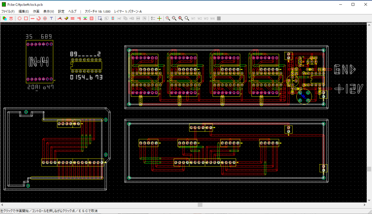
じつは当初4桁のみの予定だったので、2桁分はパターンがないけど、4桁で動作確認終わっていたので気合いで作った。
完成!!

というわけで、土日の2日間で作れたので、興味ある人おすすめです!